GENEVO PROTECTOR II
INSTALLATION MANUAL
CONTENT
User manual can be found here.
SYSTEM COMPONENTS
- 1x Main Control unit PROTECTOR II LIVE
- 1x Radar antenna with (4m wire)
- 1x GPS antenna (6m wire)
- 1x Power cable (1m wire)
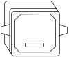
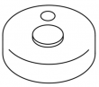
- 1x Multifunctional classic or capacitive control button (3m wire)
- 1x Speaker with (1.5m wire)
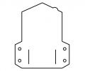
- 1x Universal radar antenna holder
- 1x Connecting material for fixing the antenna
- 1x Access Card for online system management
CONNECTION DIAGRAM
Connection diagram of individual system components: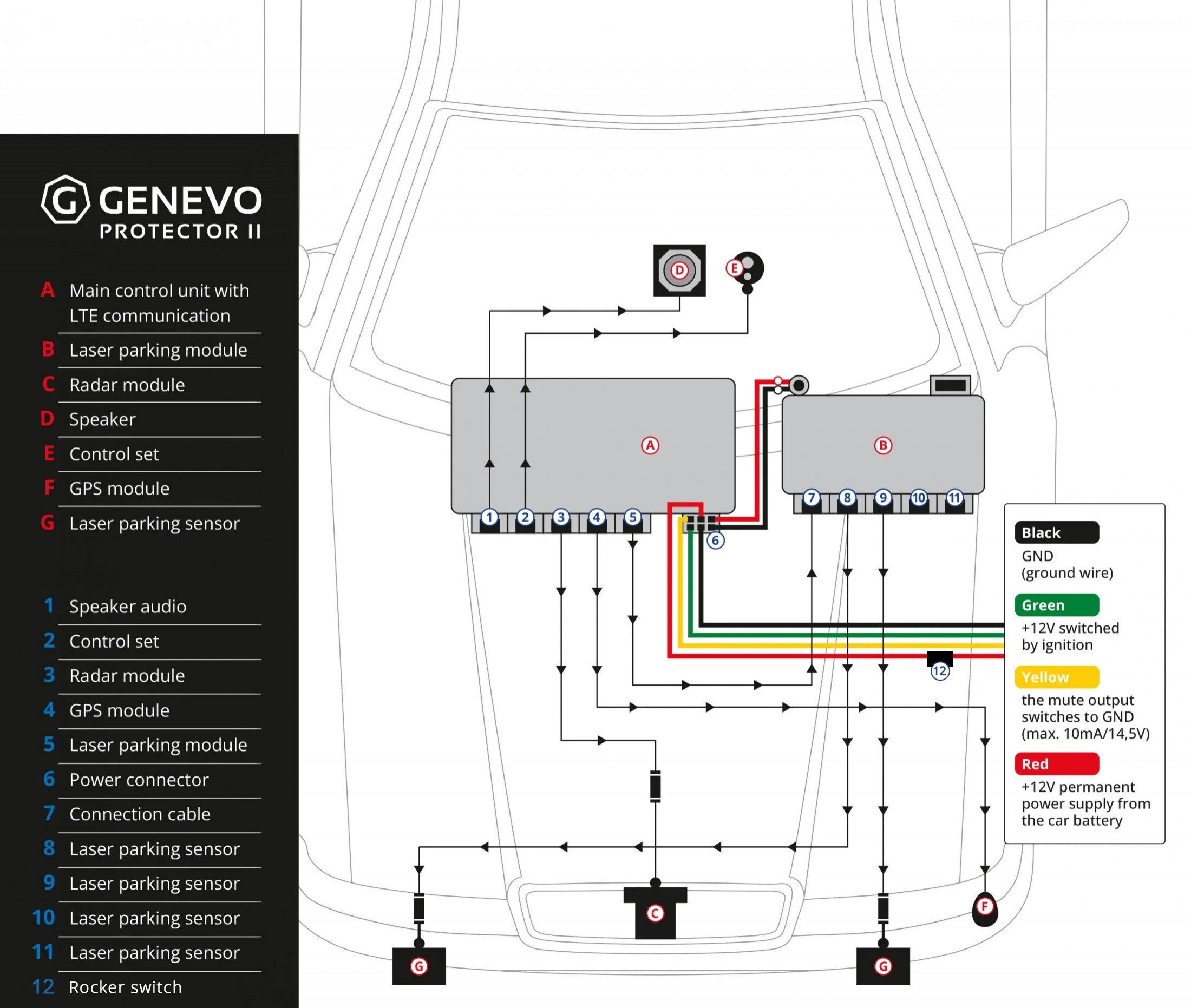
SYSTEM INSTALLATION
-
Installation can be carried out only by specialized service centers trained by the manufacturer. For information on available service centers, contact your dealer.
SPEAKER INSTALLATION
 Place the speaker in the lower compartment, behind the plastic at the feet on the driver's or passenger's side. Choose a location ensuring sufficient loudness of alerts from the speaker.
CONTROL BUTTON INSTALLATION
 Classic control button: Place the control button in a suitable place so that it is visible to the driver and can be used comfortably while driving. To install the control button, you need to drill an installation hole of 10mm. As a location, we recommend using unoccupied buttons (covers), or another suitable place in the driver's field of vision, possibly in the ashtray, or in one of the unused compartments in the car.
CAPACITIVE BUTTON WITH LED INSTALLATION
 When installing the LED diode, make sure that it does not shine directly in the driver's eyes and so that it is not directly visible. Try to hide the LED so that it creates ambient lighting, for example in the entire AC vent.
Install the capacitive button according to consultation with the customer and to the technical capabilities of the cabin. The place should be easy to remember. We recommend using a fast drying and heat resistant adhesive, ideally the same adhesive used for attaching perspex.
It is necessary to follow this sequence of steps:
- 1. Set the capacitive button control option in the settings
- 2. Turn on the PROTECTOR II
- 3. Only then physically connect the capacitive button to the unit
SAFETY ROCKER SWITCH INSTALLATION
To protect the control unit, it is necessary to install a "rocker switch" when connecting the power supply, which is placed on the red wire, see the POWER SUPPLY CONNECTION chapter. This rocker switch is in the "I" position during operation and is set to "0" in the following cases:
- When arriving at the service - it eliminates the possibility of the service questioning that the device is the cause of another malfunction on the car
- When winterizing - this will prevent the battery from discharging unnecessarily
- When starting with a booster - CAUTION, otherwise the unit will be destroyed by the increased starting current
- When solving unexpected problems - this is not a universal solution to any possible malfunction, but very often this OFF/ON operation will help the unit to start up (please follow the instructions of Genevo support)
GPS ANTENNA INSTALLATION
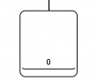 The GPS antenna must not be shaded by any metal parts (watch out for metalized and heated windshields if installing under the dashboard). Fix the GPS antenna horizontally using a suitable sealant or double-sided adhesive tape so that the upper part is facing up, ideally in the front bumper in the area around the lights, next to the brace, etc. leave a space above the antenna to approx. 5 to 10 cm, with ideally no unnecessary obstacles above it an angle of 180 degrees (typically the hood). To verify the functionality of the GPS antenna, the vehicle must be outdoors and in an open space to ensure GPS signal reception. The first activation takes about 1-5 minutes.
CONTROL UNIT INSTALLATION AND CONNECTION
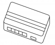 This control unit continuously evaluates the signals from the radar antenna and the other modules. The ideal placement is under the dashboard. The CPU can be attached using self-locking straps or double-sided tape. Avoid damaging the unit's serial number label. Wrapping the unit in foam is always recommended to prevent any noises under the dashboard. The connection of the individual modules must correspond to the description on the control unit or to the connection diagram. All components plugs in easily with the connectors, make sure you hear a "click" when you insert the connector into the socket.
Important notice: If you want to use the automatic startup/shutdown function based on the movement and vibrations of the vehicle, the control unit must be firmly connected to a fixed part of the vehicle. For example, glued using double-sided tape. Because there is a GSM antenna in the control unit, the back of the unit must not be near any metal part of the car.
When connecting the individual components of the system, be very careful to plug all the connectors into the appropriate sockets!
RADAR ANTENNA ASSEMBLY
 The radar antenna is extremely fine and sensitive device that captures the signals emitted by police radars, its installation location is crucial to guarantee proper functiononality and good sensitivity. The antenna is installed in the front part of the car, usually behind the plastic bumper or behind the front grille in front of the vehicle's radiator. The arrow on the antenna must point forward towards the road. It is ideal to place the antenna in the bumper vent at a height of 30-50 cm above the road and where the antenna will not be visible from the outside of the car (in the wheel arch, behind the plastic near the fog lights). If you decide to mount the antenna so that the bumper covers the front part of the antenna, make sure there is no metal reinforcement or other metal (chroming) in the bumper that would partially or completely shield the antenna.
Furthermore, it is necessary to keep the antenna as far as possible from heat sources, such as engine radiators and air condition, from which the antenna can heat up. If a safe distance from heat sources is not respected, the antenna may overheat and proper functionality can not be guaranteed. To avoid these problems, place the antenna with access to flowing air, which will cool the antenna while driving. In case of uncertainty regarding the location of the radar antenna, do not hesitate to contact your dealer.
RADAR ANTENNA MOUNTING
-
An original Antenna mount with pre-drilled holes is included in the package. For proper stability it is necessary to mount the antenna firmly, for example, use screw mounts on both sides of the antenna. However, during assembly, pay attention to possible mechanical damage to the antenna, which is not covered by the warranty! For example, too long screws (without washers) can "drill through" the antenna cover. The antenna can also be attached to the holder using a high-quality sealant. The warranty also does not cover damage caused by improper assembly or disassembly of the device (or its components). At the same time, neither the manufacturer nor the seller shall be liable for any additional costs caused by the installation or dismantling of the system.
RADAR ANTENNA CABLE
-
After attaching the antenna, connect the antenna cable using the other part of the connection connector. Pull the antenna cable to the front bulkhead between the engine compartment and the cabin. We recommend adding it to the existing wiring and attaching it with fixing straps. The antenna cable and connector are resistant to the engine compartment environment and allow for easy connection and disconnection when changing the antenna mounting location or replacing the antenna. When installing the cable, keep in mind that the cable must not touch hot parts of the vehicle and must not be installed in areas of high temperature. In particular, avoid any contact of the cable with moving parts of the engine, such as the alternator or radiator fan!
-
Use the original cable route to pull the cable into the cabin area. If there is not enough room to extend it, drill a hole and pull through the end connector with the cable. When drilling the hole, be very careful not to damage the surrounding wiring or any other part of the vehicle! When pulling through the cable, be careful not to damage the end connector! After pulling the cable through, it is necessary to secure the hole with a suitable, for example, silicone sealant to prevent moisture from entering the vehicle. Also, check that the cable is long enough to reach the desired position. The antenna cable is 4m long.
INSTALLING THE LASER MODULE
-
External sensors - can be mounted in the front grill or above the bumper, or at the back of the vehicle. Take extra care not to damage the cable or connector during installation (damage to the cable or removal of the connector will void the warranty). For a better and stealthier look of the vehicle, use a special opaque Perspex to cover the sensors. Please contact your dealer for more information.
- Use the original cable route to pull the cable into the cabin area. If there is not enough room to extend it, drill a hole and pull through the end connector with the cable. When drilling the hole, be very careful not to damage the surrounding wiring or any other part of the vehicle! When pulling through the cable, be careful not to damage the end connector! After pulling the cable through, it is necessary to secure the hole with a suitable, for example, silicone sealant to prevent moisture from entering the vehicle. Check that the cable is long enough to reach the desired position. The laser sensor cable measures 1 meter and the cable connecting the sensor to the control unit is 4 meters long. A total of 5 meters of cable can be extended by an additional 2.5 meters with an extension cable (optional accessory).
- When connecting the cables, use shrink tape in the given place to achieve moisture proofnes. Use hot air or a lighter to shrink the shrink tape. Using the included double-sided adhesive tape, fix the sensor in the holder in the desired position that offers a clear view from the front or rear of the vehicle. If necessary, you can additionally bend the holder into the desired position. Make sure the sensor is firmly mounted to withstand vibration while driving. Furthermore, make sure that the sensor is in a horizontal position (e.g. use a spirit level) and points directly in front of/behind the vehicle.
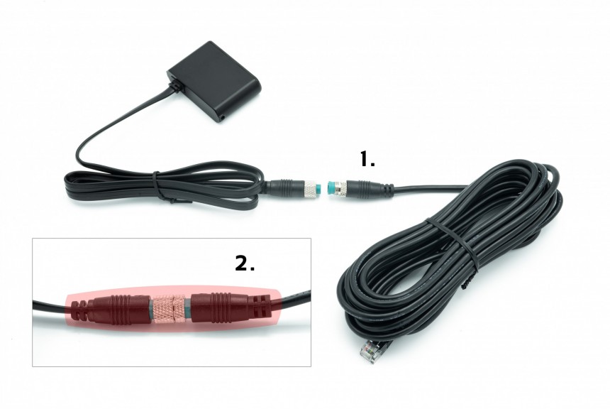
- 1. OPTIONAL: Extension cable 2.5 m.
- 2. Use transparent shrink tape on the connector to ensure 100% moisture-proofing.
-
Control unit - is installed in the interior of the vehicle under the upholstery or under the dashboard at your discretion, but only where it will not come into contact with water. Connect the power supply of the laser module control unit to the PROTECTOR control unit using the special pins. Note: 1A fuse is located in the control unit of the device. If you require an additional fuse, it can be installed externally on the wiring (not necessary). After the laser module control unit is connected to the PROTECTOR unit, connect the sensor to one of the "S" sockets. If you have more than one sensor, connect them all, the front sensor to the front and the rear sensor to the rear of the vehicle.
-
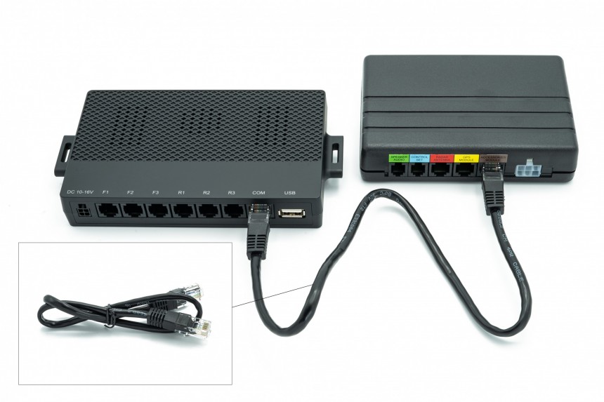
Next, connect the laser module with a communication cable to the PROTECTOR control unit (marked "Laser module", marked "C" on the laser module.
CUSTOM LASER MODULE SETTINGS
-
You can set the version of the connected laser module using the PROTECTOR II web interface. The setting is different for individual laser modules:
- GENEVO LP - there is no need to further set anything
- GENEVO FF - there is no need to further set anything
- AL Priority - If you did not receive the ALP unit in the box with the PROTECTOR II, it is probably not pre-set and there are a few basic steps that need to be taken before connecting the AL Priority to the PROTECTOR II:
- Long press the Menu button. The LED will turn yellow.
- Press the MENU button 7 times and press the Enter key. The system will go to the menu where you can enter the code 4x9 (so you enter this 4 times the same way).
- Now press the Menu button 9 times, then press the Enter key. Wait for the sequence sound. The LED is white.
- Now press the Menu button 9 times, then press the Enter key. Wait for the sequence sound. The LED is white.
- Now press the Menu button 9 times, then press the Enter key. Wait for the sequence sound. The LED is white.
- Now press the Menu button 9 times, then press the Enter key. Wait for the sequence sound. The LED is white.
- After successful entry, the green diode indicates that the Key-lock protection has been activated.
- 3. At https://www.alpupdate.com/ConfigureNew, set the AL Priority unit according to your preferences. It is necessary to set "Duration of LID protection" to "Unlimited", and "Unicam camera" for front sensors. We leave the rest of the settings up to you. We recommend turning off the parking functions. Next, according to your preferences, choose which of the possible lasers to activate.
POWER CONNECTION
ATTENTION! For proper functionality of the device, it is necessary to connect two 12V power supplies, the permanent vehicle power supply (FUSE / electric terminal no. 30) and the switching vehicle power supply (FUSE / electric terminal no. 15).
The system is powered using a connector located on the main control unit:
-
Green wire - connect the +12V power wire to electric terminal No. 15 on the vehicle (+12V after turning on the ignition key)
-
Red wire - connect the +12V power wire to electric terminal No. 30 on the vehicle (+12V permanent power supply from the car battery). (In a case there is no contact terminal with mark "15" in the car, the unit can be woken up with an integrated accelerometer).
-
Black wire - GND ground –12V (vehicle frame)
-
Yellow wire - the mute output switches to the GND of the vehicle frame during an alert. Connect this wire to the appropriate input to mute the audio system or car radio. (max output load is 50mA/14.5v)
The main control unit has installed overcurrent and overvoltage protection, however, to prevent, for example, a short circuit on the wiring, all wires connected to +12V must be protected by a 5A fuse at the power source. The manufacturer is not liable for damage caused by non-compliance with this regulation and, for example, by the subsequent occurrence of a short circuit in the wiring, which could cause the vehicle to catch fire.
CABLE CONNECTION EXAMPLES
GENEVO LP:- Power cable:
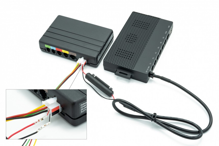
- Data cable:
TECHNICAL PARAMETERS
Certificate of the Ministry of Transport:
The Ministry of Transport of the Czech Republic issued a decision to grant the certificate: ATEST 8SDOperating frequency
- GPS: GPS, GLONASS, Galileo a QZSS
- Ka narrow: 34,0 GHz, 34,3 GHz, 34,7 GHz, 35,5 GHz (±120 MHz)
- Ka wide: 33,4 GHz ~ 36,0 GHz
- K narrow: 24,125 GHz (±70 MHz)
- K wide: 24,125 GHz (±150 MHz)
- Pulse radar (PR): Vizir, Iskra, etc.
- MultaRadar: CD/CT
- GATSO: RT3/RT4
- Stalker Phodar (PD)
- Redflex (BETA)
- DAHUA
Power supply
- Supply voltage: 11 to 15V DC
- Standby power consumption when switched off by button / standby mode /cca.10mA
- Current consumption in the switched-on state: approx. 300mA
- Maximum current consumption during an alert: 450mA / max.
- The mute output switches to GND during an alert, max. load: 10mA / 14.5V
- Operating temperature: -20 to +70°C
- Storage temperature: -30 to +80°C
- The control unit must be installed indoors for protection against water damage
- If there is no contact with the terminal marking "15", the unit is woken up by the integrated accelerometer.
Dimensions
- Radar antenna: 98.4 x 49.2 x 42.2 mm
- GPS antenna: 41 x 49 x 14 mm
- Control unit: 120 x 80 x 27 mm
- User control button: 18 x 6 mm
- Speaker: 56 x 56 x 53 mm
Warranty conditions
- During production and before distribution, the device undergoes several checks to guarantee its 100% functionality, maximum quality, and reliability. The entire system is warranted for 24 months and is valid from the date of purchase. The warranty does not cover damage caused by incorrect installation, by exceeding the maximum permitted operating voltage, incorrect electrical wiring, or by any mechanical damages. Furthermore, the warranty does not cover a water-damaged main control unit that is not built to be installed outside the vehicle interior, e.g. the engine compartment.